Super Late Model Rules
Changes Highlighted in Blue
Note: As we try to match rules with national series, we plan to follow the Lucas Oil Late Model Series and “unified” national rules for bodies and car construction as much as possible. Because of that, these rules may be modified at any time.
TIRES
- Tire Rule
- The Late Model Tire Rule will allow the following tires:
- The only legal tires will be the Hoosier NLMT 2, 3, and 4.
- On the Right Rear, the only legal tires will be the Hoosier NLMT 3 and 4.
- The Late Model Tire Rule will allow the following tires:
- Largest permitted tire is twenty-nine inches (29″) by eleven inches (11″) by fifteen inches (15″).
- Maximum circumference permitted is ninety-three inches (93″).
- Maximum cross section width permitted is sixteen and three-quarters inches (16 ¾”).
- Hoops for inspection must pass over tire freely.
- All sidewall markings must visible at all times. No buffing or removing of the compound designations.
- Chemical alterations, vulcanizing, tire softening, defacing, and/or altering the face of the tire lettering and/or tire stamping will not be permitted. Chemicals or tire softening is not permitted at any time.
Engines
A.) Only conventional type V-8 engines with the cam in the block will be permitted. Cubic inch displacement is optional.
B.) Engines must be based on a manufactured, factory design. C.) Aluminum or steel blocks will be permitted.
D.) All engines must be naturally aspirated with a single conventional-type four (4) barrel carburetor.
E.) The engine must have an operating self-starting mechanism.
F.) Only one (1) distributor or magneto is permitted. Cylinder designated individual coil systems will not be permitted.
G.) A maximum of twenty-five and one-half inches (25-1/2”) from the center of the left ball joint to the front of the motor plate/engine bell housing flange will be permitted.
H.) Only two (2) valves and one (1) spark plug will be permitted per cylinder.
I.) A harmonic balancer certified to SFI Spec 18.1 is required.
J.) No overhead cam engines.
K.) An approved carburetor roll-over plate that prevents fuel spillage in case of a roll over is highly recommended.
Transmission, Driveline, and Driveline Components
Transmission
A.) A functional clutch must be used. Direct drive systems of any type will not be permitted.
B.) The transmission must be bolted to a bellhousing, bellhousing must be bolted to the engine.
C.) The transmission must have forward and working reverse gear(s) and must be able to shift to forward or reverse with the engine running.
D.) Only two speed transmissions with a working reverse low gear and high gear will be allowed. High gear is 1 to 1.
D.) No overdrive or underdrive multiple speed transmissions will be permitted.
Driveshafts
A.) All drive shafts must be a minimum of two inches (2”) in diameter. All drive shafts must be painted white.
B.) Only one (1) driveshaft connected from the transmission to the center section of the rear end will be permitted.
C.) A minimum of one (1) driveshaft hoop/sling must be fastened securely to the frame.
Read End
A.) Any type of rear end differential / center section will be permitted.
B.) No independent rear suspensions are permitted.
C.) Full-floating hubs manufactured of either aluminum or magnesium with “wide 5” wheel bolt pattern must be used.
D.) The axle housing must be of the “closed tube” design utilizing “full floating” magnetic steel axle shafts.
E.) The center section of the axle housing must be manufactured of either aluminum or magnesium.
F.) Axle tubes must be one (1) piece. Axle tubes must be manufactured of aluminum or magnetic mild steel. Axle tubes manufactured of exotic heavy materials will not be permitted. The outside diameter of the axle tubes must not exceed three (3) inches. Axle tube internal inserts or external sleeves will not be permitted. The addition of any ballast weight to the axle housing will not be permitted.
G.) All axle housings using a cable to lock-in the rear-end must have the cable mounted outside the cockpit area and not in reach of the driver.
Fuel, Fuel Cells, and Fuel System
A.) All fuel cells must meet or exceed the FIA / FT3 or SFI 28.3 specifications. The fuel cell may only have a maximum capacity of 35 gallons, prior to foam.
B.) The fuel cell must be enclosed completely in a container that is a minimum thickness of 20-gauge magnetic steel and/or .060”-inch aluminum.
C.) Fuel cell cap must be a threaded cap and/or ATL Part # TF751 1/4 Turn Bullet Cap, Schultz Racing Fuel Cell part #SFP-300 quarter (1/4) turn cap.
D.) The entire container must be visible for ease of inspection.
E.) The fuel cell must be mounted behind the rear axle between the rear tires, a minimum of 4”-inches ahead of the rear bumper. The bottom of the fuel cell must not be any lower than the bottom of the rear end/quick change housing.
F.) Fuel cells that are not contained within a welded steel tubing “rack” must have two (2) equally space straps that measure two inches (2”) wide by one eighth inch (1/8”) in thickness that surround the fuel cell. The straps must be bolted to the frame. Longitudinal (front to rear) orientation is recommended for strap mounting.
G.) Fuel valve plate, fuel pickup, and fuel return fittings must be on the top of the fuel cell.
H.) Only racing gasoline or alcohol will be permitted for competition. Nitrous oxide, nitromethane and/or propylene oxide will not be permitted.
I.) Competitors must be prepared to drain fuel from the fuel cell for inspection.
J.) Mechanical fuel pumps must be used. Fuel pumps must be engine mounted. Fuel pumps may be camshaft actuated or belt driven. Electric pumps, primary and/or secondary, pressure systems, and additional reservoirs will not be permitted.
Electrical Systems, Batteries, and Electrical Accessories
A.) The battery must be securely mounted with positive fasteners and brackets. All battery supports and/or mounts must be secure and braced in two (2) horizontal positions and one (1) vertical position.
B.) The battery terminals must be insulated, and the battery enclosed with a non-conductive material that will prevent contact with any part of the race car should the battery become dislodged from the battery mount.
C.) One (1) mandatory battery disconnect switch must be installed on the rear deck, behind the driver seat, in a location that is easily accessible from outside the race car. The switch must be clearly labeled with off/on direction. The switch must be directly in-line with the NEGATIVE battery cable and be capable of completely disconnecting the NEGATIVE terminal of the battery from the race car. Negative or “ground” wiring connections must not be made anywhere from the battery negative terminal to the input side of the disconnect switch.
D.) No batteries are permitted in the driver’s compartment/ cockpit.
Ignition Boxes, Exhaust, Muffler, and Sound Reduction Devices
A.) The exhaust flow must be parallel to the ground. Exhaust systems that direct the flow toward the ground will not be permitted.
B.) All exhaust systems/headers must end with a collector.
Ignition Boxes, Traction Control, Radio, and Transmission Devices
A.) All electronic and/or computerized wheel spin and/or ignition retardation and/or acceleration limiting and/or traction control devices of any type will not be permitted.
B.) Adjustable ping control devices, dial a chip controls, timing controls, and/or automated throttle controls will not be permitted.
C.) Adjustable restrictor plates will not be permitted.
D.) Remote control components of any type will not be permitted.
E.) Radios and/or devices for transmitting voice and/or data will not be permitted.
F.) Data acquisition systems will not be permitted.
G.) GPS and/or any type of electronic tracking and/or locating devices will not be permitted.
Chassis and Frame
Chassis
A.) The minimum wheel base will be 103”-inches with a maximum wheel base of 105”-inches.
B.) Frames fabricated using square tubing must be a minimum of 2”-inches x 2”-inches or approved rectangular magnetic steel with a minimum material thickness of .083”-inches.
C.) Frames fabricated using round tubing must be a minimum of one and three quarters of an inch (1-3/4”) outside diameter magnetic steel tubing, 4130 chrome moly, Docol, or DOM with a minimum material thickness of eighty-three thousandths of an inch (.083”).
D.) Rear bumpers that are stubbed may only extend a maximum of 8”-inches beyond the frame. Any stubbed rear bumper that extends further than the maximum of 8”-inches must be formed and directed 8”-inches toward the front of the car.
E.) All battery supports and/or mounts must be secure and braced in two (2) horizontal positions and one (1) vertical position.
F.) The manufacturer’s unique serial number should be displayed on every chassis.
G.) No aluminum frames, door bars, or bumpers permitted.
H.) No titanium fasteners, or chassis and suspension components.
Roll Cage
A.) All cars must have a roll cage fabricated from a minimum of 1-1/2” outside diameter with .065”-inch thick seamless magnetic steel tubing.
B.) The side roll bars and/or door bars must extend into the door panels.
C.) A minimum of three (3) 1-1/2” outside diameter bars .065”-inch in thickness must be utilized on the left side of the car in the door area.
D.) Roll cage must be above the driver’s helmet thirty-eight inches (38”) minimum between floor pan and the bottom of the roll cage.
E.) The entire roll cage must be constructed of round tubing only.
Driver Side Intrusion Plate
A.) A minimum 1/8″ (.125”) thick magnetic steel intrusion plate on the driver’s side door bars is mandatory. B.) Approved Installations:
i.) Welded plates- Individual plates between door bars are permitted but must be weld around the perimeter of each opening. Minimum area covered is 16inches by 26 inches.
ii.) A minimum of 16” x 26” plate bolted to fabricated 1/8” (.125”) magnetic steel tabs, welded securely to the chassis, using a minimum of eight (8) x 3/8” Allen button head bolts. A minimum of three (3) fabricated 1/8” (.125”) magnetic steel tabs and 3/8” Allen button head bolts required across top of the intrusion plate, a minimum of three (3) fabricated 1/8” (.125”) magnetic steel tabs and 3/8” Allen button head bolts required across the bottom of the plate, and one (1) fabricated 1/8” (.125”) magnetic steel tabs and 3/8” Allen button head bolt in each in the middle front and middle rear of intrusion plate.
iii.) A minimum of 16” x 26” plate bolted to a minimum of six (6) approved-design door bar clamps using the included 12 x 1/2” Allen button head bolts per the manufacturer’s specification. A minimum of three (3) approved-design door bar clamps and the included six (6) x 1/2” Allen button head bolts required across top of the intrusion plate and three (3) approved-design door bar clamps and included six (6) x 1/2” Allen button head bolts required across bottom of intrusion plate. Vendor and part number must be clearly labeled on part.
iv.) Current approved-design door bar clamps
1.) Allstar Performance – Part Number: ALL4198
2.) Bicknell Racing Products – Part Number: BRP 954
3.) Wehrs Machine & Racing Products – Part Number: WM397
Weight and Ballast
A.) A minimum weight limit of 2350lbs for Aluminum blocks and 2300lbs for Steel blocks will be in effect. Cars with factory sealed GM CT525 engines will be allowed to weigh 2250 lbs.
B.) No Burn Off allowance will be given.
C.) Any attached weights must be securely attached to the frame, painted white or bright silver, and have the car number clearly displayed on them. All weights must be secured by two (2) half inch (1/2”) Grade 5 or higher bolts on two (2) weight clamps per piece.
D.) Additional added weight(s) must be securely attached to the frame below the body decking.
i.) Frame is defined as the steel welded structure only.
E.) Any part that moves or is not a fixed component to the steel frame structure may not be used for any weight attachment.
F.) Additional added weight(s) attached to the rear bumper and/or outside the frame will not be permitted.
G.) Any car that loses any weight/ballast during an event may be subject to a penalty.
H.) Pellet-type and/or liquid-type weight/ballast will not be permitted.
I.) Driver operated weight adjustment, ‘weight jacking’ devices will not be permitted.
J.) The scale(s) used for the event, provided by the track will be considered the official scales for the event.
K.) Scale(s) will be available for all teams to verify their car weight and determine the scale weight.
J.) In the event of a car not meeting the required overall weight, Officials may allow a car to re-weigh up to (2) two additional times by removing the car from the scale(s) and repeating the weighing procedure. If a car is allowed to re-weigh the overall weight of the car recorded during the final weighing procedure will be the “official” weight of the car.
Bodies
General Body
A.) All cars must have a minimum one-half-inch (1/2”) and a maximum of one inch (1”) radius at the top of fenders, doors, and quarter panels. Sharp edge(s) will not be permitted.
B.) The floorboards and firewall must completely cover the driver’s area with no openings.
C.) Fins and/or lips of any type will not be permitted anywhere along the entire length of the car.
D.) Wedge shape cars and/or body styles will not be permitted.
E.) “Belly pans” or any type of enclosure on the bottom of the car will not be permitted. A skid plate to protect the oil pan is permitted. A maximum one-eighth inch (1/8”) skid plate will be permitted.
F.) Wings and/or tunnels and/or any type of air deflection device will not be permitted underneath the body and/or chassis of the car.
G.) A maximum of one (1) stone deflector, for rear mounted oil pumps, oil filters, and for the main oil tank will be permitted. The deflector may be made of steel, aluminum, or heavy gauge wire. The cover may only be mounted near the unit it is designed to protect with a maximum size of eighteen-inch (18”) x eighteen inch (18”) and only mounted from the upper right frame rail to the lower right frame rail.
H.) Panels of any type under the rear deck running from the front to the rear of the car will not be permitted.
I.) Any style air cleaner scoop used must be positioned in front of/or around the air cleaner and must not exceed one inch (1”) in height above any part of the air cleaner. Any type of flange and/or air deflection device and/or fin that is designed to direct airflow will not be permitted.
J.) The top edge, measured from the ground, of the rear quarter, door, and front fender to the point where the fender flare attaches must be a straight line, within one inch (1”) on both sides of the car.
K.) All body panels must be solid. No holes, slots, or air gaps are permitted. NACA ducts or NACA style ducts are not permitted. One (1) hole for interior (deck) mounted oil cooler is permitted.
L.) The minimum ground clearance (including plastic) is three inches (3”).
Nosepiece
A.) Only approved nosepieces will be permitted. Currently approved nosepieces:
i. Dominator (must fit MD3 template)
ii. MD3 – Performance Bodies
iii. ARP Air Speed Nose
iv. Five-Star MD3 type
v. Performance Bodies/Five Star MD3 2015
vi. Performance Bodies / Five Star 2016 Evolution
vii. Performance Bodies / Five Star 2019 Evolution 2
B.) Approved nose assemblies must be installed per the manufacturer’s instructions. All nose assemblies must meet the maximum/minimum dimensions, maintain manufacture appearance, and not be altered.
C.) All nosepieces must be made of molded type material.
D.) Nose filler panel shall be flat across to entire surface, dishing or raising is prohibited.
E.) Two-piece noses must be positively fastened together in the center. Spacers added to gain width will not be permitted.
F.) The nosepiece must be mounted flat where filler panel and nosepiece meet. The nosepiece must be mounted in a manner that does not alter its original shape. The nosepiece will be checked with a template by pushing against the mounting supports to gauge its profile against the template.
G.) Holes for cooling purposes must be within ten inches (10”) from the center point of the nose (where the left and right panels of nose and/or valance come together).
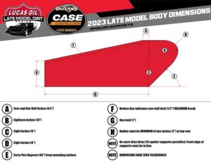
H.) The nosepiece can extend a maximum of fifty-three inches (53”) from the center of the front hub to the farthest point extending forward.
I.) The front fender flairs can extend a maximum of four inches (4”) above the filler panel or the hood.
Roof and Roof Supports
A.) The roof length size must be a minimum of forty-four inches (44″) to a maximum of fifty-four inches (54″).
B.) The roof width size must be a minimum of forty-eight inches (48″) to a maximum of fifty-two inches (52″).
C.) Roof must be mounted directly to the roll cage with no spacers.
D.) The minimum height of the roof will be forty-five inches (45”) with a maximum height of forty-eight inches (48”).
E.) The roof must be mounted parallel to the body and near the center of the car.
F.) A maximum one and one-half inch (1-1/2”) roll, turned downward will be permitted along the front edge of the roof. A maximum one inch (1”), ninety-degree (90°) bend, will be permitted along the rear edge of the roof. These modifications will be permitted to improve the strength of the roof. Any other modifications to the roof will not be permitted.
G.) Flat and/or odd shaped roofs will not be permitted. Bellied and hollowed roofs will not be permitted.
H.) Sun/anti-glare shields may not be used.
I.) A maximum of two (2) roof edge bead rolls of a maximum height of 1⁄2”-inch the length of the roof will be permitted.
J.) The maximum thickness of the roof at any point will be 1⁄2”-inch.
K.) The roll cage and associated frame members above the interior panels (decking) must remain open. Enclosures will not be permitted.
Roof Supports and Window Side Panels
A.) All roof side panels must extend to the edge of the body.
B.) The left and right sail panels must be between fifteen inches (15”) and seventeen (17”) at the top; between forty inches (40”) and forty-three (43”) inches at the bottom.
C.) The window area may be covered with clear Lexan or transparent material. Both window openings must be covered, or both must be left open.
D.) If sail panels are left open, they must maintain a border frame of two inches to three inches (2-3”) at the top and sides, and three inches (3”) at the bottom.
E.) The maximum inside radius of either sail panel is three inches (3”).
F.) The left and right-side window panels must match.
G.) A maximum bow of two inches (2”) outward on the window side panels as viewed from behind will be permitted.
H.) The front roof supports must extend forward to the rear of the hood. The front roof supports may be a maximum of 4”-inches wide. The left and right front roof supports must match.
I.) A minimum of three inches (3”) is required between sail panel and spoiler support.
Front Fenders, Fender Flares, and Hood
A.) The hood must be level and flat from the left to the right side of the car.
B.) The hood can drop two inches (2”) measured at the back edge of the hood and in from of the carburetor from the left to the right side of the car. Fenders must taper from outer edge to the hood in a straight line.
C.) The fender top must have a ten inch (10”) minimum width.
D.) The outside edges of the hood and/or the fender must remain inside the overall bodyline.
E.) The front fender must be a minimum of thirty-six inches (36”) and maximum of thirty-eight inches (38”) in height, measured vertically from the ground to the top of the fender behind the front tires.
F.) The front fender flares must be made of plastic and must not alter the original shape of the nose piece.
G.) The front fender flares must not extend beyond the front tires more than one inch (1”) per side to a maximum width, edge-to-edge, of ninety inches (90”) with the wheels pointed straight.
H.) Front fender flairs must not extend, bubble, or rise more than four inches (4”) at any point of the front fenders and/or hood.
I.) The front fender flares must have collapsible supports.
Doors
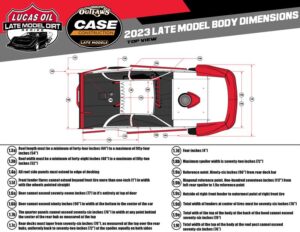
A.) The door-to-door measurement must not exceed seventy-seven inches (77”) in width at the top of the doors.
B.) The door-to-door measurement must not exceed ninety inches (90”) in width when measured at the bottom of the doors in the center of the car (including plastic).
C.) The doors must not exceed thirty-seven (37”) in height when measured from the ground to the top of the door.
D.) The door sides may not bow inward more than one inch (1”) from top to bottom (including plastic).
E.) Plastic door panels are permitted on the right side only.
Quarter Panels
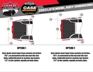
A.) The maximum distance from the center of the rear hub to the top quarter of the panel is fifty-four inches (54”).
B.) The quarter panel must not exceed seventy-six inches (76”) in width at any point as measured at the top of the panel.
C.)The rear deck must taper from where the quarter panel and door meet to the rear spoiler with a minimum width of seventy-two inches (72”) and a maximum width of seventy-six inches (76”).
D.) The maximum width for the quarter panels measured from outside-to-outside (including plastic) is eighty-two inches (82”).
E.) The quarter panels may not break inward more than one inch (1”) from top to bottom (including plastic).
F.) The maximum distance from the center of the rear hub to the rear trailing edge of the quarter panel is forty-nine inches (49”).
G.) A minimum of two inches (2”) of tire clearance between the tire and the body will be required.
H.) Left rear wheel opening between the quarter panel and the door must be a minimum of twenty-eight inches (28”) with a maximum of thirty-three inches (33”).
I.) Right rear wheel opening between the quarter panel and the door must be a minimum of twenty-nine inches (29”) with a maximum of thirty-two inches (32”).
J.) Skirting that extends behind the rear quarter panel will not be permitted.
K.) Left rear quarter panels must extend downward from the deck a minimum of thirty-three (33”) and a maximum of thirty-six inches (36”) (including plastic) when measured at the front and rear of the quarter panel.
L.) The right rear quarter panel must extend downward from the deck twenty-seven inches (27”) without plastic, or thirty-one inches (31”) with plastic when measured at the front and rear of the quarter panel.
M.) Deck height will be measured at the nose piece splitter at a max height of fifteen inches (15”) from the ground to the top. Deck height must be thirty-nine inches (39”) from the top of the rear deck to the ground. n. Plastic quarter panels are permitted on the right side only.
Right Side Body
A.) The quarter panel, door, and fender (to the fender flair) must be within one inch (1”) of a straight line in all directions when measured at the top of the body.
B.)The quarter panel and door must be within one inch (1”) of a straight line where the skirting joins the door and quarter panel.
Spoilers, Spoiler Braces, and Spoiler Supports
A.) Only aluminum and/or Lexan and/or Lexan-type rear spoilers will be permitted.
B.) The maximum overall height of the rear spoiler will be 8”-inches. The maximum width of the rear spoiler, including braces and/or supports is 72”-inches.
C.) The rear spoiler must begin at the deck and extend 8-1/4”-inches from that point. Mounting hardware, hinges, etc. will be included in the 8-1/4” inch measurement. Suspending the spoiler to create a wing-type device will not be permitted.
D.) The rear spoiler must begin at the rearmost point of the quarter panels.
E.) Only three spoiler braces/supports will be permitted. The front edge of the spoiler brace/support must be in line with the spoiler.
F.) The outside spoiler supports must not be mounted any wider than the top of the quarter panel(s) and must be centered on the rear deck.
G.) In the event that aluminum angle is used to brace the upper edge of the spoiler, the angle must not add to the height and/or length of the spoiler in any way.
H.) The spoiler must be a single plane from top to bottom.
Interior
A.) The interior is permitted to be dropped to the middle (just behind the seat) of the car a maximum of five inches (5”) below the top of the doors and minimum of twelve inches (12”) below the roll cage.
B.) The side window opening(s) must be fifteen inches (15”) from the top of the door to the bottom of the roof.
C.) Support bars that block the right window from the driver exiting the cockpit will not be permitted.
D.) A rock guard (Lexan screen) can be no higher than four inches (4′′) and no farther back than the front edge of the right-side headrest.
E.) If the interior is dropped at firewall/back of the hood, that portion of the firewall must be filled in vertically with aluminum. Interior may be dropped a maximum of two inches (2”) from the top of the hood.
F.) Interior must be fastened flush at the top of the door and quarter panels and must taper gradually towards the center of the car at a maximum of seventy-degree (70°) angle from the deck.
G.) Interior must run in a straight line (vertical and horizontal) across the back of the car at the spoiler.
H.) All interiors must be made of aluminum.
Driver Compartment
A.) A full metal firewall fabricated from magnetic steel and/or aluminum must encompass the driver’s compartment from front-to-rear, on both sides and floorboards.
B.) All cars must be equipped with a quick-release type steering wheel that is a full circle.
C.) Mirrors of any-type will not be permitted.
D.) Radios and/or electronic and/or data communication devices will not be permitted.
E.) Any edge and/or sheet metal end in and around the driver compartment must be protected with trim and/or beading and rounded. Sharp and protruding edges will not be permitted.
F.) A rock guard with a minimum of three (3) additional roll bars must be mounted in front of the driver.
G.) Cockpit adjustable components except for brake bias adjusters will not be permitted. Adjusters of any- type, including but not limited to adjustable shocks, hydraulic or pneumatic weight jacks, trackers, ignition boxes or similar adjustable components will not be permitted inside the cockpit of the car or within reach of the seated driver.
Body Skew
A.) The measurement of the left rear quarter panel from the center of the hub to the rear of the quarter panel cannot exceed fifty-four inches (54′′). Measuring seventy-two inches (72′′) from the left rear quarter panel to the right rear quarter panel, then ninety-six inches (96′′) forward along the right side door, the diagonal measurement from that point to the top of the left rear quarter panel must be a minimum of one- hundred seventeen inches (117′′).
Brakes, Brake Components, Wheel Hub
A.) Must be equipped with sufficient four (4) wheel braking system. On-track three (3) wheel braking is allowed.
B.) Brake calipers must be manufactured of aluminum.
C.) The brake caliper including brake caliper pistons must be used as produced by the brake caliper manufacturer.
D.) Brake rotors must be manufactured of magnetic or stainless steel.
E.) Brake rotors must be used as produced by the brake rotor manufacturer.
F.) Wheel hubs must be manufactured of aluminum or magnesium.
G.) Wheel hubs must be used as produced by the wheel hub manufacturer.
H.) The combined weight of the wheel hub, wheel bearings and seal, spindle nut and washers, brake rotor and attaching hardware, the axle cap, and the wheel spacer must not exceed 27 pounds.
Suspension, Suspension Components, Spring, Shocks, and Steering
General
A.) Rear suspension designs and applications are constantly evolving. Although the intent of the rear suspension rules is an attempt to accommodate most of the suspension and suspension component designs and applications currently being used in competition, the rules cannot be absolute. All new designs or modifications to an existing suspension and/or suspension component must be communicated to and approved by the Technical Director before being used in competition.
B.) Rear suspension must utilize either coil or leaf springs.
C.) Rear suspension configuration used on current and new chassis(s) must be the design commonly known as four (4) link. Older cars currently competing with other rear suspension designs will be allowed to compete until further notification at the discretion of the Technical Director.
D.) Swing arm and/or Z-Link suspension types are permitted. The shock on a swing arm or z-link rear suspension may mount to the bird cage or bottom radius rod. Top and bottom solid links must be mounted on hiems and run in the opposite direction of the bird cage.
E.) Bump sticks are not allowed anywhere on the car.
Front Suspension
A.) All cars must utilize independent front coil spring suspension consisting of (1) one right and (1) one left lower control arm, (1) one right and (1) one left upper control arm, (1) right and (1) one left spindle, (1) one right and (1) left shock, and (1) one right and (1) one left spring / spring stack.
i.) Lower control arms must be fabricated using magnetic mild steel or 4130 chrome moly tubing.
ii.) Lower control arms may be of the “A” frame design with (2) two inner pivots or the Ford design with (1) one inner pivot and a strut rod to secure the control arm fore and aft movement. The strut rod may be mounted either forward or rearward of the control arm.
iii.) All lower control arm frame mounts must be welded to the applicable frame rail. (The right lower control arm mounts must be welded to the right-side frame rail and the left lower control arm mounts must be welded to the left side frame rail.) This procedure applies to the Ford style including the strut rod as well.
iv.) Lower control arm mounts, (inner pivot points) must remain to the outside of the front frame centerline for the respective side.
v.) The frame mounts for the lower control arm inner pivots may be adjustable by (2) two methods:
1.) A series of single round holes.
2.) A machined slot that will accept a steel “slug” with a single round mounting hole(s).
vi.) Both methods of mounting must produce a secure non-moveable mount when assembled and tightened.
vii.) Upper control arms must be fabricated using magnetic mild steel or 4130 chrome moly tubing.
viii.) Upper control arms may be either the “A” frame type design with or without a shaft or the individual tube type with individual inner pivot mounts.
ix.) All upper control arm frame mounts must be welded to the applicable frame rail. (The right upper control arm mounts must be welded to the right-side frame rail and the left upper control arm mounts must be welded to the left side frame rail.)
x.) The frame mounts for the upper control arm inner pivots may be adjustable by optional methods including but not limited to:
1.) A series of single round holes.
2.) A machined slot that will accept a steel “slug” with a single round mounting hole(s). 3.) A machined slot with a capture eccentric (cam) type adjuster.
xi.) All methods of mounting must produce a secure non-moveable mount when assembled and tightened.
xii.) Spindles must be fabricated or forged using magnetic mild steel.
xiii.) If separate, spindle steering arms must be welded to the spindle.
xiv.) Steering arms must remain below the spindle pin.
xv.) Spindles must connect to the upper and the lower control arms by utilizing ball joints, mono- balls, or spherical rod ends.
Rear Suspension Frame Mounts
A.) The frame/roll cage structure must have integral welded mounting brackets for the attachment of rear suspension components. Frame suspension mounts may be welded or bolted securely (without any movement) to the frame/roll cage structure.
B.) The only materials used to fabricate frame suspension mounts that will be permitted are magnetic steel or aluminum.
C.) Frame suspension mounts must be double shear configuration for mounting suspension components. Shear mounts must use minimum five-eighths of an inch (5/8”) rod ends with minimum one-half inch (1/2”) grade eight (8) bolts only. The bolt must be bolted through both shear mounts.
D.) Double shear frame suspension mounts must be a minimum of three-sixteenths of an inch (3/16”) thickness on both sides of the mount. Double shear mount must be no wider than four inches (4”) with a minimum one-half inch (1/2”) grade eight (8) bolt with steel or aluminum spacers only.
E.) All frame suspension mount component mounting holes must be round and sized correctly for the fastener being used. Clearance between the fastener and the mounting hole must not exceed the next fractional drill size. Example: 1/2-inch fastener, 33/64-inch mounting hole.
Axle Housing Mounts
A.) Only one (1) axle-housing mount per side will be permitted.
B.) The only materials used to fabricate axle housing mounts (birdcages) that will be permitted is aluminum or magnetic mild steel. Axle housing mounts fabricated of exotic; heavy materials will not be permitted.
C.) When fabricating axle housing mounts, detail must be paid to functionality. The completed axle housing mounts, when comparing the right and the left side, must be as similar in design as possible.
D.) Axle housing mounts may be a solid (welded) type or a floating type (birdcage) design.
E.) The final assembled axle-housing mount must be a one (1)-piece mount. When a floating type of mount (birdcage) is fabricated using two (2) pieces, the two (2) pieces must create a common one (1)-piece pivot (barrel). The two (2) pieces must be fastened or welded together to prevent independent movement of the two (2) pieces. The axle-housing mount must attach directly to the axle tube with clearance only to permit rotation of the entire mount. Fore, aft, or vertical movement of the mount or the axle housing within the mount will not be permitted.
F.) Mounts for suspension attaching (radius) rods must be an integral part of the axle-housing mount. The mounts may be either a single or double shear configuration. When using a single shear configuration, a minimum thickness of 1/4 inch for magnetic steel or 1/2 inch for aluminum is required. When using a double shear configuration, a minimum thickness of 3/16 inch for magnetic steel or 1/4 inch for aluminum is required. Dynamic movement of any mount other than a rotating and pivoting movement because of suspension travel will not be permitted.
G.) Unless otherwise authorized by the Technical Director, the mounting of any component(s) other than suspension attaching (radius) rods or shocks will not be permitted on the axle housing mounts.
Rear Suspension Attaching (Radius) Rods
A.) A maximum of two (2) attaching (radius) rods per side will be permitted.
B.) The only materials used to fabricate attaching (radius) rods that will be permitted are magnetic steel or aluminum.
C.) Attaching (radius) rods may be solid or tubular material. The material may be round or hexagon in shape.
D.) Spherical rod ends, or steel clevises must be used at the end of each rod for pivoting, static length adjustment, and mounting. Bushings of any type will not be permitted.
E.) The final assembled attaching (radius) rod must not have the capability to change length dynamically by any means or devices.
F.) Spherical rod end sizes may be a minimum of a 5/8-inch rod end body with a 1/2-inch bearing to a maximum of a 3/4-inch rod end body with a 3/4-inch bearing.
G.) In all applications, the correct size fastener must be used when mounting the spherical rod end to a bracket (example: 1/2-inch fastener must be used with a 1/2-inch bearing and mounting hole). Metal step spacers will be permitted to reduce the hole size of the spherical rod end bearing.
H.) Attaching (radius) rods must mount directly to the frame suspension mount at the forward end and to the axle-housing mount at the rearward end.
I.) All rear suspension fasteners must be magnetic steel with a minimum diameter of 1/2 inch. The use of grade 8 fasteners is highly recommended. All fasteners must be correctly sized for the component and application of use.
J.)When rear suspension assembly is completed:
i. Attaching (radius) rods must be spaced on the frame a minimum of six inches (6”).
ii. Attaching (radius) rods must be spaced on the birdcage a minimum of six inches (6”) and a maximum of twelve inches (12”).
iii. Measurements will be made from the center of each attaching (radius) rod bolt.
K.) All attaching (radius) rods must be straight with the exception of the left lower that can have a bend for axle housing mount clearance.
Rear Travel Limiter (Droop Rule)
A.) A vertical travel limiting chain must be installed on the left rear of the car from the left rear axle housing to the frame. The travel limiting chain must attach to a bearing type mount or a clamp mounted bracket with the chain mounted to the top (12 o’clock) of the left rear axle tube, between the birdcage and the edge of the left rear bell of the axle housing, and to the left rear frame directly above the chain mount on the rear axle. Travel limiting chains must be installed so that when taunt they are as close to vertical as possible. One (1) compliance device may be used. The compliance device must not be more than one inch (1′′) thick (without a load applied) and remain completely open and visible. Compliance devices can be rubber or any like material but must not be installed in any type of canister. Springs, spring-loaded, and/or pneumatic devices will not be permitted. No tapered, beveled, or roller skate type of compliance rubber will be permitted. Compliance devices must be solid material, same diameter top to bottom, not hollowed or drilled to soften the material.
B.) The travel limiting chain including the compliance rubber must be installed so that when the car is jacked up from the rear the chain assembly is tight (no slack).The travel limiting chain is subject to inspection at any time during the event at the discretion of the officials. Cars will be jacked up on the under-slung frame rail between the center of the rear axle and the panhard bar mount. The left rear under-slung rail must be located between the left rear birdcage and the edge of the left rear axle housing bell. If a chassis is not of the under-slung design, then the car will be jacked up on the left rear frame rail closest to the Panhard bar mount. Cars will be jacked up until a forty-thousandths of an inch (.040”) shim will slide between the left rear tire and the ground. Once the car is jacked up as described a vertical measurement will be taken from the ground to the top trailing edge of the rear deck bar, six inches (6”) inboard of the left rear quarter panel outer edge. The measurement must not exceed fifty-one inches (51”). (Cars without a left rear underslung must not exceed fifty inches (50”)).
C.) All droop limiter assemblies must support the unsprung mass of the rear-end. The stretched value of the droop limiter assembly may be no more than three-quarters of an inch (3/4”) at 1,200 lbs. The procedure: preload 100 lbs. zero (0) distance, pull to a value of 1,200 lbs.
Torque Control Devices
A.) Lift arm assemblies and pull bars will be permitted.
B.) Only one (1) torque control device may be used.
C.) Lift arms must attach to the axle housing using a mounting configuration that prevents any movement between the lift arm and the rear axle housing. A gusset or brace bar to prohibit side-to-side flex will be permitted.
D.) The forward end of the lift arm may use a spring over shock assembly (5th coil), a spring or bushing, and a limiting chain.
E.) Pull bars may be adjustable on both ends; however, the adjustments must remain fixed during competition. Adjustors within reach of the driver will not be permitted. No hydraulic or pneumatic pull bars will be permitted.
Springs
A.) The front suspension must use magnetic steel coil springs.
B.) The rear suspension may use coil or leaf springs. The coil springs must be magnetic steel. Leaf springs may be either magnetic steel or a composite material.
C.) Coil springs may be used individually or stacked.
Shock Absorbers
A.) Shocks are intended to dampen and help control spring frequencies in both the compression and rebound motions. The amount of force applied to move the shock piston and shaft assembly may be varied with the option of shock “builds” however the piston and shaft assembly must have the ability to move in both directions.
B.) Mono-tube, single piston, nitrogen gas charged shocks will be permitted. All shocks must utilize mechanical oil controls, such as: spring shim(s), drum and disc(s), check ball and spring, needle and seat for internal and external shock adjustments. Magnetic and/or electro-magnetic controls are not permitted. Remote nitrogen gas reservoirs will be permitted. The remote reservoirs may contain a compression adjustor. Adjustments described above are the only shock adjustments that will be permitted.
C.) Shock adjustments while the vehicle is in motion will not be permitted.
D.) Shocks and shock components may only be manufactured from steel or aluminum.
E.) Rotating parts will not be permitted inside or mounted to the shock absorber. Inertia/gyro style shocks are not permitted.
F.) Thru-rod shocks will not be permitted.
G.) Unless otherwise authorized, all shocks must be mounted as close to vertical as possible.
H.) Approved shock locations are as follows:
i.) One (1) shock will be permitted at each front wheel.
ii.) One (1) shock will be permitted at the right rear wheel.
iii.) Two (2) shocks will be permitted at the left rear wheel. When using only one (1) shock at the left rear wheel, the shock must be mounted behind the rear axle tube. When two (2) shocks are used at the left rear wheel, one (1) shock must be mounted behind the rear axle tube and the second shock must be mounted on top of or forward of the rear axle tube.
iv.) One (1) shock will be permitted mid-ship at the front of the lift arm assembly.
v.) One (1) braking shock will be permitted. The shock must be mounted within three (3) inches of the center line of the rear axle center section. This shock must be mounted horizontally.
I.) Air shocks are permitted.
J.) Maximum shock body outside diameter is two and one-half inches (2-1/2”).
K.) Maximum front shocks length is twenty-one inches (21”), measured center to center of the shock eyes.
L.) Maximum rear shocks length is twenty-seven inches (27”), measured center to center of the shock eyes.
M.) No electrically adjusted or active dampers are allowed. No electrical wires, transmitting, or receiving components will be allowed to be attached internally or externally to the dampers or mounted inside any component or dampers. No portion of the car including but not limited to – shocks and spring components or chassis components – may have the ability to communicate, transfer, transmit, receive any type of digital or analog data or any language and/or adjust or monitor in any way whatsoever including but not limited to a variation of a wireless remote device, phone, computer, tablet, or a mechanical remote device.
N.) Suspension covers are not allowed. Rear covers on the car are not allowed outside of your pit area. Spring and/or shock covers are permitted but must be fastened directly to the spring or shock.
Steering Components, Wheels, and Tires
Steering Components
A.) Only one power steering pump allowed. Electronic steering and/or electronic steering components will not be permitted.
Wheels
A.) Only aluminum wheels will be permitted for competition.
B.) The wheels must be mounted to the hubs utilizing lug nuts. “Knock off” and/or single type wheel mounting systems will not be permitted.
C.) The maximum wheel width that will be permitted is 14”-inches.
D.) The combined weight of the wheel, wheel hardware, wheel disc and fasteners, and tire must not exceed 40 pounds.
E.) The maximum front track width will be 90”-inches and the maximum rear track width will be 88”-inches, measured from the outside edge of the tire to the outside edge of the tire.
F.) Only approved wheel discs will be permitted. Approved wheel discs are wheel discs that are fastened to the wheel using a minimum of three (3), 1/4 or 5/16-inch diameter magnetic steel hex head bolts. The use of wheel discs with any other type of fastener will not be permitted.
G.) Only aluminum wheel spacers will be permitted.
H.) Wheel/Air Bleeders are not allowed.
Safety Equipment
Seats
A.) All seats must be full containment type constructed of aluminum or carbon fiber (SFI 39.2 rated) to the general design specifications of SFI 39.2 standards. Design shall include comprehensive head surround, shoulder and torso support system, and energy impact foam.
B.) SFI 39.2 certified seats are required for all drivers. All drivers will receive three (3) full weekends grace period before required compliance.
C.) A non SFI 39.2 seat with bolt-on kits will be permitted with a seat manufacturer produced kit and a base seat acceptable to the seat manufacturer. Components must include a comprehensive head surround, shoulder and torso support system and energy impact foam. Must be installed in accordance with the seat manufacturer’s instructions. Non SFI 39.2 seats must be made of aluminum.
D.) Seats must be used as supplied and instructed by the seat manufacturer.
E.) Seats must be mounted to a seat frame that is welded to the race car frame/roll cage structure. Attaching points, angles, and materials for the seat frame and mounting of the seat to the seat frame must be in accordance with the seat manufacturer’s instructions.
F.) Seat mounting brackets must use properly sized bolts and washers for the hole in the bracket. No oversized holes or slotted holes in the bracket. No spacers or washers stacked.
Restraint Systems
A.) The use of a five (5), six (6) or seven (7) point driver restraint system certified to SFI Spec 16.1 or 16.5 is REQUIRED, no exceptions. All driver restraint systems shall not be more than two (2) years of age past the date of manufacture. The use of a seven (7) point driver restraint system is strongly recommended. All mounting points of the racing harness MUST be mounted properly in accordance with the manufacturer’s instructions, and securely mounted to the chassis with the use of grade five (5) or better hardware.
Window Nets
A.) Window nets certified to SFI Spec 27.1 or safety nets certified to SFI Spec 37.1 are strongly recommended and must be mounted in accordance with the manufacturer’s instructions and technical director’s satisfaction.
Drive Line
A.) A drive line “sling” is REQUIRED.
Helmets
A.) A helmet certified to Snell SA2015/FIA–8859–2015, Snell SA2020/FIA–8860–2018, SFI 31.1/2015 or SFI 31.1/2020 is required to be always worn during competition or on the racing surface.
Driver Suits
A.) A driver suit certified to SFI Spec 3.2A/5 is REQUIRED to be always worn during competition or on the racing surface.
Gloves
A.) Gloves certified to SFI Spec 3.3 are REQUIRED to be always worn during competition or on the racing surface.
Socks and Shoes/Boots
A.) Socks and Shoes certified to SFI Spec 3.3 are REQUIRED to be always worn during competition or on the racing surface.
Cockpit Tubs
A.) Eighteen (18) gauge steel or one and one-eighth inch (1 1/8″) aluminum “cockpit tub” to protect front, sides and rear of the driver is HIGHLY RECOMMENDED.
Head and Neck Restraints
A.) Head and neck restraint devices/systems are REQUIRED.
B.) At all times during an event (practice, time trials, and competition), drivers must connect their helmet to a head and neck restraint device/system certified to SFI Spec 38.1. The device/system must display a valid SFI Spec 38.1 label. The head and neck restraint device/system, when connected, must conform to the manufacturer’s mounting instructions, and must be configured, maintained, and used in accordance with the manufacturer’s instructions
C.) It is the responsibility of the driver, to ensure that his/her device/system is certified to SFI Spec 38.1, correctly installed, maintained, and properly used.
Fire Suppression
A.) All race cars must be equipped with a thermally deployed automatic fire suppression system. The fire suppression system will consist of a DOT approved cylinder manufactured from aluminum or steel with a capacity of ten pounds (10lbs.) of fire extinguishing agent, steel, or steel reinforced lines, and two (2) thermally activated discharge nozzles.
B.) All systems must meet or exceed SFI 17.1 specifications.
C.) Systems must be fully charged with ten pounds (10lbs.) of DuPont FE-36, 3M NOVEC 1230, or Fire Aide and display a legible and valid SFI and manufacturer label depicting fire extinguishing agent, capacity, and certification date. Cylinders that are beyond useful certification date must be inspected, serviced, and re- labeled by the manufacturer.
D.) Cylinders must be mounted forward of the fuel cell. Cylinders must be securely mounted to the frame/roll cage assembly. The certification label must be unobstructed and easily accessible for inspection when the mounting is complete.
E.) The cylinder must be connected to the nozzles with steel or steel reinforced lines.
F.) Two (2) thermally activated nozzles must be used. One (1) nozzle must be located directly above the fuel cell in the fuel cell area and the second nozzle must be in the driver cockpit area. An optional engine bay nozzle may be added.
G.) An optional manual override cable may be added to the system.